

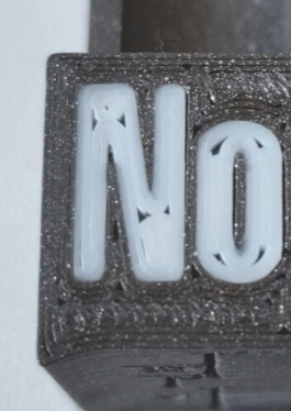
They happen when lines meet where the width of the feature isn’t an exact multiple of the extruder’s width and the printer has trouble filling in the void. Usually they’re fairly invisible, but when printing white on black, they stand out like a sore thumb.
I’m wondering if there’s a good simple way of avoid this problem in the slicer. The ultimate fix of course is to print a square sheet of white PLA under the white letter, but I’d rather not mess with my model because it’s quite complex already.
You must log in or register to comment.

Comments did not disappoint.
We could be witnessing the birth of a meme!
Set your slicer to only use one wall for the top layer. Edit: also, calibrate your extrusion. This looks like slight underextrusion to me.
Solid suggestions, they could also try turning on ironing if the above doesn’t produce satisfactory results.
I would say under-extrusion would probably make ironing less attractive in this case depending on why there was under-extrusion.Would help, but I think it would still be subpar.
Right: Ironing would be for after they fixed extrusion and only if they still didn’t like how it looked.
I finally had time to look into this - in the slicer at least - and I think you’re right: one wall should solve the issue. I can tell just by how the slicer arranges things. I turned on ironing too for the topmost layer. That should make it even better.
I’ll go to the office to start the print today. It takes about 5 hours - and 20 more minutes just for the ironing of that one surface 🙂 I’ll let you know how it goes.
Thanks for the suggestion!
Looks like you answered your own question. :)
This is a fairly common complaint with the output produced by any slicer using the Arachne perimeter generator, which includes Prusa and its derivatives by default now, and also Cura.
If you are using Prusa or a derivative you can switch back from the Arachne perimeter generator to Classic in your “Layer and Perimeters” tab. If you can’t stomach not using Arachne for whatever reason, you could try messing with the “Perimeter Transitioning Threshold Angle” setting. There is some additional wordage on all of the above here. TL;DR: The Arachne generator attempts to build perimeters out of variable line widths and explicitly does not go back and fill in tiny voids like these with a separate operation. The point is that it’s not supposed to have to, but as you can see it doesn’t always work out that way.
As others have pointed out, doing an ironing pass on your top layer may help conceal this from an aesthetic standpoint but won’t do anything for you structurally (i.e. for anyone running into this issue with a shape they hope to be watertight). The nuclear option would be to instruct the slicer to do an ironing pass on every layer which may help your print look boss at the end of things but will certainly also take forever.
Arachne perimeter generator to Classic
Yes I do use arachne. I did try to change it to classic when I was messing with my 3D-printed lens experiment, and while arachne wasn’t perfect, it left fewer artifacts inside the “lens” than classic.
I’ll try to revisit classic for this one print.
doing an ironing pass on your top layer may help conceal this from an aesthetic standpoint but won’t do anything for you structurally
I’ll try ironing, This one is purely an esthetic problem. The part is just a cover for a case that holds electronic bits inside.
Try YES next time :p

If someone asks you if you’re a god, you say YES!
deleted by creator
Does your slicer have Arachne slicing mode? It will use variable extrusion width which will help to prevent most of those gaps.
2 replies pretty much in opposition to each other. So which one is correct? One says Arachne might be the cause, the other says to use that to fix the issue.
You can set the minimum extrusion width to a small value (20-25%) for better fill. You could also use classic mode with gap fill. You can use ironing for both to improve the results.
Arachne is more cleverer but more susceptible to poorly tuned settings (than the classic slicing engine)
Which slicer are you using? You can try setting ironing to on and the wall generator to arachne
other than what is already suggested, could be the top layer pattern you are using. try some different ones
To me it looks like tuning your pressure advance might help.
https://ellis3dp.com/Print-Tuning-Guide/articles/pressure_linear_advance/introduction.html
I’ll look into this. Thanks!
Print vertically or at a 30-45 degree angle
There is less material than needed all over the place, look at the not bonded perimeter lines on the top corner.
Measured the real filament diameter before printing and corrected the slicer settings to the measured diameter?
Are the extruder steps calibrated?
If iam to lazy to reslice, i would increase feedrate to around 106% and look at the following layers if the gaps are closed mid print.
This can be seen at layer 2 and corrected while printing
Measured the real filament diameter before printing and corrected the slicer settings to the measured diameter?
Are the extruder steps calibrated?No and I don’t even know how to do that 🙂 The printer is the company’s Prusa XL and we’re using it as it came out of the box. I’m normally very happy with what it churns out, it’s just that small esthetic issue on a part that bears the company logo, that we intend to sell to customers.
I’ll look into that. Thanks!
Im only familiar with Cura. Cura has wall settings I think you are looking for to fix your problem. I had similar issues with a print. Used settings like wall transition length, wall distribution count, wall transitioning threshold angle, wall transitioning filter margin, and minimum wall line width. I was able to fill in tight corners, just took a little while dialing in the settings.
Write your gcode by hand and you can do curves thus ensuring lines won’t meet. I last wrote gcode by hand in the 1990s, and I’m pretty sure industry stopped hand gcode around 2000 (before 3d printing), but the language isn’t difficult and so you can do it.
Couldn’t I at least punch it out on a card?
You could do that too. I’m not old enough to punch cards but that doesn’t need to stop you.
Hand code is still used. Most frequently, a sub is hand coded with incremental moves and then called at a point. A lot of probing, weird moves, edge cases all still get hand coded.
Hand editing CAM produced programs constantly occurs at the machine as well.
3D printing gcode is pretty ugly because hobbyists “improved” the language without really understanding why it was so stripped down.
Modern Gcode is really meant to be machine generated and human readable/editable.
Use something other than FDM 3d printing - SLA (resin) printers have higher resolutions and will not have those issues. Or you could put a solid sheet of plastic on a mill and use subtractive machining to make your parts. There are a few other options.
All options have pros and cons, and your best answer might be just live with it (see other replies for ways to mitigate the issues). However don’t get locked into 3d printing just because it is the “in” thing.


